

How To Install A Sending Unit In A Fuel Tank
Is your fuel guess inaccurate? Is information technology no longer working at all? This is a common problem on older boats, just is easy to fix. The first pace is to make up one's mind whether the problem is with the judge or the sending unit of measurement. The examination for this is straightforward. First, check that the estimate is receiving 12 volts of power. Turn on the engine'southward ignition and probe with a multimeter between the ground and the positive final on the back of the gauge; it should be marked with a "+" or an "I." If there is no voltage then the error is in the ignition circuit—and the gauge is probably expert. If in that location are 12 volts at the gauge, either the sender, the estimate or its wiring is the culprit, so you need to proceed to the next pace.
With power running to the gauge, disconnect the sending wire; it will be marked with an "Southward" at the back of the gauge. One time the wire is disconnected, the judge should bound to its highest possible reading. If this is the case and then the gauge is practiced and you can proceed to the side by side step. If the gauge does not reach its maximum reading, it is faulty and must be replaced.
Another test is to jump a wire or a screwdriver across the sending pivot to the ground pivot on the back of the gauge. If there is no ground pin, utilize a longer wire and bound the sending pivot to the engine block. When you do this, the gauge should get to its everyman reading. If it does, it is working properly.
If the gauge is good, the next step is to check the other organisation components, as either the wire running to the sender or the sender itself must exist faulty. To cheque the wire, disconnect it from both the sender and the "Southward" pin on dorsum of the gauge. Set your multimeter to the Ohms scale and bank check the resistance within the wire. If there is no resistance (as shut to zilch Ohms equally possible), the excursion is practiced and the sender is faulty. In most cases, the sender and the fuel gauge need to be matched to the resistance in the sender'south rheostat, so to be completely certain you are getting accurate readings, replace both the sender and the gauge. Several companies provide pre-packaged "ready-to-get" installation kits.
How Tank Sensors Work
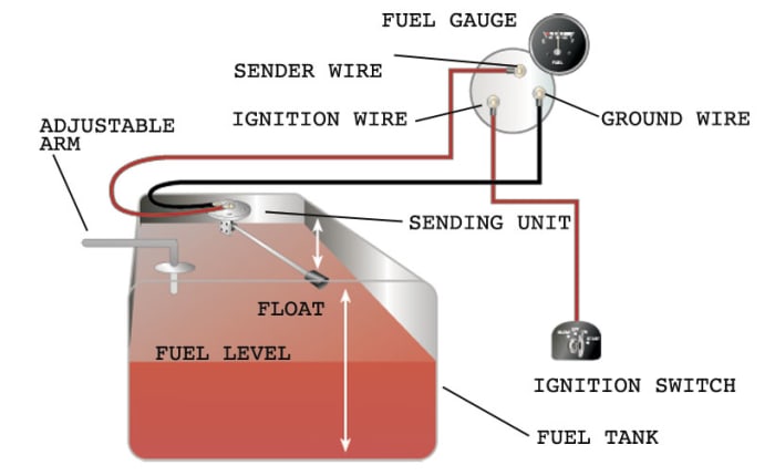
Well-nigh sensors have a mechanical floating arm and a rheostat. When the arm is all the way downward, in the "empty" position, the resistance in the excursion to the gauge is nearly zero. As the arm rises, resistance in the excursion also rises to around 200 Ohms. This resistance is what moves the needle on the gauge.
Frequently a problem occurs when the sending unit'south floating arm becomes inoperative. On older units the floats may be made of cork. Over time these floats can lose buoyancy or even sink altogether, causing the fuel estimate to point that the tank is constantly empty.
Another common problem results when the rheostat doesn't transmit the correct electrical current to the fuel judge, even though the floating arm is moving upward and downwardly properly. In this case, both the sender and the judge demand to be replaced.
Left: My new sending unit installed. The sending wire leads off the center postal service; the other wire runs to basis. Note the marks I made to align screw holes (dark) and the bladder arm inside the tank (in pencil).Correct: The new fuel judge. The wire marked "+" runs to the engine's ignition switch. The center wire is ground; the one on the correct is the sending wire.
Sender Installation
Having obtained a new fuel sender kit, yous should follow the directions specific to your new unit. In general, installation will involve the post-obit steps. Note that senders are not normally "plug and play" units. The length of the sender arm may take to be modified to fit the dimensions of your fuel tank. This also ensures that the guess reads properly.
Offset measure tank depth from the tiptop of the tank, well-nigh the sending unit of measurement, to the bottom. This measurement determines the length of the sending unit of measurement's float arm. Adjacent, trim the kit'south sending unit arm—they usually come in 24in lengths—and match it to the tank depth. A strong pair of wire cutters volition work with most units, but some require a hacksaw. In one case yous take cut the float arm to the right length, fasten information technology with setscrews to the flange of the new sending unit that will be screwed into the height of the tank.
The sending wire volition come up off a post in the center of the flange. In that location may also be a footing wire coming off a second post at the edge of the flange. Both wires lead to the back of the fuel approximate. Turn off the power running to the boat's systems before you disconnect any wires. So disconnect both the sending wire and basis wire on the old sending unit. Note that if the judge is grounded straight to a tab on the tank, there may exist no ground wire. Remove the screws that agree the sending unit of measurement to the tank and take it out.
Next, remove the 3 wires on the back of the old estimate. One wire goes to the center pin on the tank sending unit, one goes to basis, and the third connects to a 12-volt source, normally the ignition switch. Remove the fuel gauge.
Install the new sender by lowering the float and float arm into the tank. Exist sure to slide a new gasket into place under the flange, so align the gasket with the holes in the sender and in the tank. When the gasket is aligned, marking it in relation to the flange, every bit it may turn while you are centering the spiral holes to match the tank holes. Mark the spiral holes in the tank for easier alignment; the flange will comprehend them and make them difficult to locate. Bank check to be sure the bladder arm can move freely and will not stick in a corner of the tank or against a vertical wall.
Orient the sender unit and so the bladder arm'south move is not hindered. You tin can cheque this alee of fourth dimension by holding the sender next to the tank before y'all install it to see which way the float can move freely. Once you know the proper orientation, indistinguishable it when you lot put the unit in the tank. To minimize confusion, use a marking to evidence the management of travel of the bladder arm once the screw holes are aligned. Put in the new screws and tighten them down.
Fuel Gauge
Bank check the wiring diagram that comes with the kit and mark the dorsum of the new fuel gauge with symbols for each post: "S" for the sender, "K" or "—" for the ground, and "I" for the ignition. Install the new gauge, reconnect the wiring and plough on the power. The fuel gauge should at present show the correct fuel level in the tank. To make sure the readings are accurate top off the tank.
Troubleshooting
Problems often involve incorrect grounding and inadequate ability. If the guess does not read at all, check the power with a multimeter at the gauge terminal. Test between the positive concluding on the fuel approximate and a good ground; the reading should be 12 volts. If information technology isn't, check the ignition circuit. If that reads 12 volts, turn off the ignition. And then apply the Ohm calibration on your multimeter to check continuity between the ground terminal on the gauge and ground; the reading should be at or near nix Ohms. If not, recheck the ground excursion.
When everything is working properly, your new fuel approximate volition give yous a proper reading. Now you lot tin can relax, even if at that place is no wind, as you will now know whether you have enough fuel for your iron genny to carry y'all dwelling safely.
Resources
Vetus Maxwell, vetus.com
AB Marine, ab-marine.com
BEP Marine; bepmarine.com
Faria Marine Instruments, faria-instruments.com
Livorsi Marine, livorsi.com
Mirax Fuel Products, miraxfuelproducts.com
VDO,vdo.com
Westberg Manufacturing, westach.com

Source: https://www.sailmagazine.com/diy/test-replace-fuel-gauge-sending-unit
Posted by: brownforall.blogspot.com
0 Response to "How To Install A Sending Unit In A Fuel Tank"
Post a Comment